
Introduction
The 555 timer LED blinking circuit is one of the most common beginner projects in electronics. It shows how the 555 timer integrated circuit can be used to produce continuous pulses that switch an LED on and off automatically. Because of its simple design and reliable performance, the 555 timer IC is widely used in many timing and oscillation applications.
In this project, the 555 timer operates in astable mode, which means the output continuously alternates between HIGH and LOW states without needing any external triggering signal. Due to this switching action, the LED connected to the output pin turns on and off repeatedly at a regular interval.
This project is widely used by students and beginners to understand basic electronic concepts such as oscillators, timing circuits, capacitors, resistors, and the working of integrated circuits. It also serves as a foundation for learning more advanced electronic and embedded system projects.
Components Required
To build the LED blinking circuit using a 555 timer IC, the following components are needed:
- 555 Timer IC
- LED (Light Emitting Diode)
- Two resistors (used for timing control)
- One capacitor
- Breadboard for circuit assembly
- Connecting wires
- DC power supply (5V–12V)
All of these components are inexpensive and easily available, which makes this project ideal for students, hobbyists, and beginners in electronics.
Circuit Diagram:
Circuit Diagram Explanation
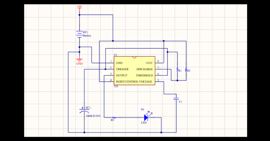
The circuit is designed by configuring the 555 timer IC in astable multivibrator mode. In this configuration, pin 1 of the IC is connected to ground, while pin 8 is connected to the positive supply voltage. Pin 4 is also connected to the supply voltage to keep the timer enabled.
The timing section of the circuit consists of two resistors (R1 and R2) and a capacitor (C1). These components determine how quickly the capacitor charges and discharges. The repeated charging and discharging process causes the output voltage of the timer to alternate between high and low levels.
An LED is connected to pin 3, which is the output pin of the 555 timer, through a current-limiting resistor. When the output becomes HIGH, current flows through the LED and it lights up. When the output changes to LOW, the LED turns off. This cycle repeats continuously, creating a blinking effect.
Working Principle
The operation of this circuit is based on the astable multivibrator mode of the 555 timer. In this mode, the timer continuously generates a square wave signal without requiring an external trigger.
The resistor-capacitor (RC) network controls the timing of the output signal. The capacitor charges through the resistors until it reaches a specific voltage level. Once this level is reached, the internal comparator inside the 555 timer changes the state of the output.
During the charging period of the capacitor, the output becomes HIGH, which turns the LED ON. When the capacitor discharges, the output switches to LOW, turning the LED OFF. This process repeats again and again, causing the LED to blink continuously.
The blinking rate depends on the values of the resistors and capacitor. Larger values increase the delay and make the LED blink more slowly, while smaller values reduce the delay and produce faster blinking.
Applications of LED Blinking Circuit
The LED blinking circuit using a 555 timer has many practical uses in electronics. It is often used in indicator systems, warning signals, decorative lighting, and simple signal generators. The circuit can also be used to test LEDs and demonstrate basic circuit operation in educational environments.
In many electronic devices, blinking LEDs are used to display system status, power indications, or fault conditions. The 555 timer provides an easy and economical way to generate these flashing signals.
Conclusion
The 555 timer LED blinking circuit is a simple and effective electronics project for beginners. With only a few basic components, it is possible to build a circuit that generates continuous pulses and makes an LED blink automatically. This project helps learners understand the principles of timing circuits and provides a strong starting point for exploring more advanced electronics and embedded system designs.