
Introduction
The Automatic Street Light using an LDR is a simple electronics project that shows how lighting can be controlled automatically based on environmental conditions. In this circuit, a light sensor called an LDR (Light Dependent Resistor) detects the surrounding light intensity and controls a light source accordingly.
In many places, street lights are turned ON and OFF manually. This sometimes leads to unnecessary power consumption when lights remain ON during the daytime. An automatic lighting system solves this problem by switching the lights ON only when the surroundings become dark.
The LDR is the key sensing component used in this project. Its resistance changes according to the amount of light falling on its surface. When the light intensity is high, its resistance becomes low. When the light level decreases, its resistance increases. This property allows the circuit to detect day and night conditions and control the light automatically.
This project is widely used as a beginner-level experiment in electronics. It helps students understand how sensors, transistors, and basic automation systems work together in a practical circuit.
Components Required
The following components are needed to build the automatic street light circuit:
- LDR (Light Dependent Resistor) – 1
- NPN Transistor (BC547) – 1
- LED – 1
- Resistor 220Ω – 1
- Resistor 10kΩ – 1
- Breadboard – 1
- Jumper wires – Few
- 9V battery or DC power supply – 1
These components are inexpensive and easily available, making the project suitable for students and hobbyists.
Circuit Diagram:
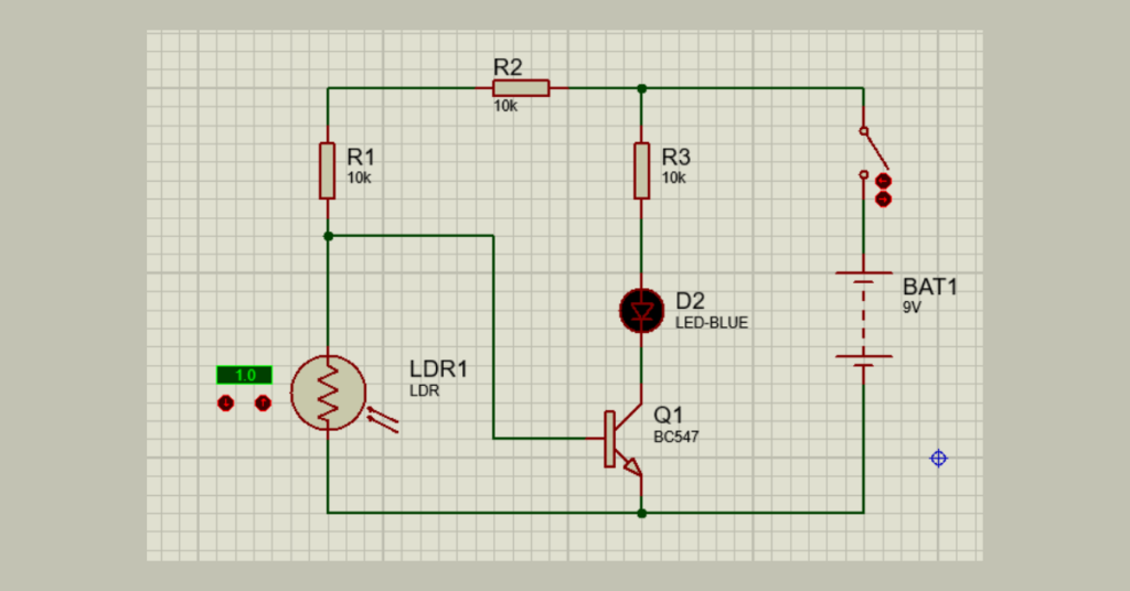
Circuit Explanation
The circuit mainly consists of an LDR, a transistor, resistors, and an LED that represents the street light.
The LDR and the 10kΩ resistor are connected together to form a voltage divider circuit. This section senses the amount of light present in the environment and produces a voltage that depends on the brightness level.
This voltage is applied to the base terminal of the transistor. The transistor works as an electronic switch that controls the LED.
When there is enough light in the surroundings, the resistance of the LDR becomes low. Because of this, the voltage reaching the transistor base is not sufficient to activate it, and the LED remains OFF.
When the environment becomes dark, the resistance of the LDR increases. This causes a higher voltage to appear at the transistor base, turning the transistor ON. Once the transistor conducts, current flows through the LED and it begins to glow.
In this way, the LED automatically turns ON in darkness and switches OFF when there is sufficient light.
Working Principle
The operation of this circuit depends on the light-sensitive nature of the LDR.
During the daytime, sunlight falls on the LDR and reduces its resistance. This results in a low voltage at the base of the transistor, preventing it from switching ON. Therefore, the LED remains OFF.
At night or in low-light conditions, the LDR resistance increases significantly. This change raises the voltage at the transistor base, which activates the transistor.
When the transistor turns ON, it allows current to pass through the LED. As a result, the LED lights up automatically.
This process ensures that the light operates only when it is needed, reducing energy consumption.
Output Result
After assembling the circuit and connecting the power supply, the LED responds to the surrounding light conditions.
- When bright light falls on the LDR, the LED stays OFF.
- When the LDR is covered or placed in darkness, the LED turns ON.
This behavior represents how an automatic street lighting system works.
Advantages
- Helps save electrical energy
- Eliminates the need for manual switching
- Simple and low-cost design
- Easy to build and understand
- Ideal for beginners learning electronics
Applications
The automatic street light circuit can be used in several practical applications, including:
- Street lighting systems
- Garden lighting control
- Outdoor security lights
- Corridor or pathway lighting
- Energy-efficient lighting solutions
Conclusion
The Automatic Street Light using LDR is a practical electronics project that demonstrates how lighting systems can be controlled automatically using environmental sensing. By combining a light sensor with a transistor switch, the circuit can detect changes in brightness and control a light source without manual intervention.
This project is especially useful for students and beginners who want to learn about sensors, transistor-based switching, and automation in electronic circuits. It also shows how simple electronic designs can contribute to energy-saving and smart lighting systems.