
Introduction
A rain alarm is a small electronic project designed to detect rainfall and notify people using a buzzer or alarm sound. It is widely used as a beginner electronics project in schools and colleges because it demonstrates the basic working of sensors and simple electronic circuits.
Rain detection devices can be useful in many situations. For example, they help people quickly move clothes indoors when rain starts or alert farmers about sudden rainfall that may affect crops. The system works by detecting water droplets on a sensing plate. When rainwater touches the sensor surface, it creates an electrical connection that activates the alarm.
This project requires only a few simple components and is easy for beginners to build. It helps students understand how electronic components such as transistors and sensors operate in a practical circuit.
Components Required
To build a rain alarm circuit, the following electronic components are required:
- Buzzer
- NPN Transistor (BC547 or equivalent)
- Resistor (1kΩ or 10kΩ)
- Battery (5V or 9V power supply)
- Rain sensor plate (two metal strips or a rain sensing module)
- Connecting wires
- Breadboard or PCB board
These components are low-cost and can be easily purchased from local electronics stores.
Circuit Diagram
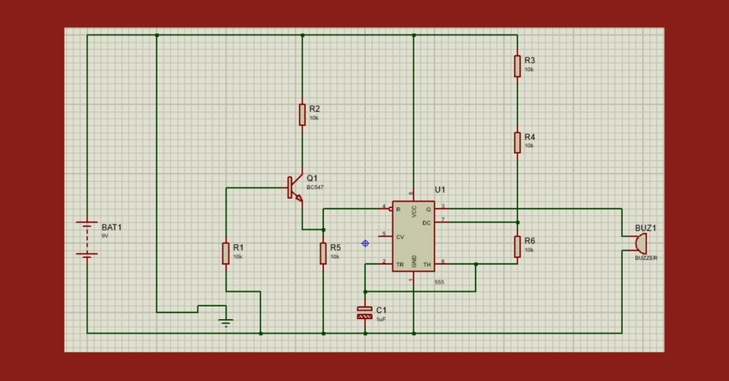
Circuit Explanation
The rain alarm circuit mainly consists of a rain sensor plate, a transistor, and a buzzer. The sensor plate usually contains two metal strips placed close to each other but not touching.
When the sensor surface is dry, the circuit remains open and no current flows through it. As soon as raindrops fall on the sensor plate, water creates a conductive path between the two metal strips.
This small electrical signal reaches the base of the transistor. Once the transistor is activated, it allows current to flow through the buzzer, which produces a sound to indicate that rain has started.
Procedure
Step 1: Gather the Components
Collect all the required components including the buzzer, transistor, resistor, battery, sensor plate, wires, and breadboard.
Step 2: Arrange Components on Breadboard
Place the transistor and resistor onto the breadboard so that connections can be made easily without soldering.
Step 3: Connect the Transistor
Attach the emitter terminal of the transistor to the ground line. Connect the collector terminal to the negative terminal of the buzzer.
Step 4: Connect the Buzzer
Join the positive terminal of the buzzer to the positive terminal of the battery or power supply.
Step 5: Connect the Rain Sensor Plate
Link the rain sensor plate to the base of the transistor through a resistor. Position the sensor in an area where it can receive raindrops.
Step 6: Power the Circuit
Provide power using the battery or power supply. Check that all connections are properly made.
Step 7: Test the Circuit
Sprinkle a few drops of water on the sensor plate. When water connects the metal strips, the buzzer will sound, indicating rainfall detection.
Working Principle
The rain alarm operates based on the electrical conductivity of water. Rainwater can allow a small amount of electrical current to pass through it.
When raindrops fall onto the sensor plate, they bridge the gap between the metal strips, completing the circuit. This allows current to reach the transistor base. The transistor then switches ON and enables current flow through the buzzer, producing an alert sound.
Once the sensor dries, the connection breaks and the buzzer stops.
Applications
Rain alarm systems are useful in several areas, such as:
- Weather monitoring devices