
Introduction
A Controlled Voltage Source (CVS) is an active electronic source whose output voltage is controlled by another voltage or current present elsewhere in the circuit. Unlike an independent voltage source, a controlled voltage source depends on an external control signal to generate its output. Controlled voltage sources are widely used in analog circuits, operational amplifier models, electronic filters, signal processing, and control systems.
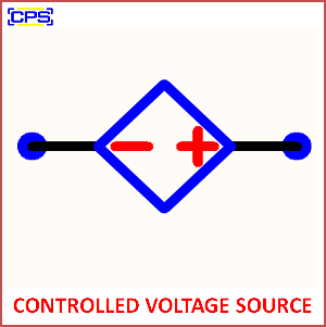
In circuit analysis, controlled voltage sources are represented using a diamond-shaped symbol, indicating that the source is dependent on another circuit variable. These sources are essential in modeling electronic devices such as transistors, operational amplifiers, and integrated circuits.
What is a Controlled Voltage Source?
A Controlled Voltage Source is a dependent source that produces an output voltage proportional to a controlling voltage or current elsewhere in the electrical circuit. The output is determined by a gain factor that defines the relationship between the controlling signal and the generated voltage.
Mathematically,
Output Voltage = Gain × Controlling Signal
The controlling signal may be either a voltage or a current, depending on the type of controlled source.
Types of Controlled Voltage Sources
1. Voltage-Controlled Voltage Source (VCVS)
A Voltage-Controlled Voltage Source (VCVS) generates an output voltage proportional to an input control voltage.
Equation
Vout = Av × Vin
Where:
- Vout = Output Voltage
- Vin = Input Control Voltage
- Av = Voltage Gain
Applications
- Operational Amplifiers
- Analog Signal Amplifiers
- Instrumentation Circuits
- Voltage Amplification Systems
2. Current-Controlled Voltage Source (CCVS)
A Current-Controlled Voltage Source (CCVS) produces an output voltage proportional to an input current.
Equation
Vout = Rm × Iin
Where:
- Vout = Output Voltage
- Iin = Input Current
- Rm = Transresistance Gain (Ω)
Applications
- Current Sensing Circuits
- Transimpedance Amplifiers
- Sensor Signal Conditioning
- Current Measurement Systems
Working Principle
A controlled voltage source continuously monitors the controlling signal in the circuit. Based on the specified gain factor, it generates an output voltage that changes proportionally with the control signal. If the control signal increases or decreases, the output voltage changes accordingly, making the source dynamic and responsive.
For example, if a VCVS has a gain of 5 and the input control voltage is 2 V, the output voltage becomes:
Vout = 5 × 2 = 10 V
Similarly, in a CCVS, if the transresistance is 100 Ω and the controlling current is 20 mA, then:
Vout = 100 × 0.02 = 2 V
Symbol
The symbol of a Controlled Voltage Source is represented by:
- Diamond-shaped source symbol
- Positive (+) and Negative (–) output terminals
- Control voltage or current is indicated separately
- Output voltage is proportional to the control variable
Features
- Dependent voltage source
- Output controlled by another circuit variable
- High accuracy
- Linear voltage amplification
- Essential for analog circuit analysis
- Used in transistor modeling
- Supports feedback control systems
- Easy mathematical representation
- Ideal for simulation and design
- Widely used in electronic circuits
Advantages
- Precise voltage control
- Improves circuit flexibility
- Simplifies electronic modeling
- Essential for amplifier design
- Supports automatic control systems
- Enables feedback implementation
- High reliability
- Accurate circuit simulation
- Suitable for analog and mixed-signal circuits
- Easy integration into complex systems
Disadvantages
- Requires an external control signal
- Cannot operate independently
- Gain errors affect output accuracy
- More complex than independent sources
- Sensitive to control signal variations
Applications
- Operational Amplifier Design
- Electronic Amplifiers
- Analog Signal Processing
- Active Filters
- Feedback Control Systems
- Communication Systems
- Sensor Interface Circuits
- Instrumentation Systems
- Power Electronics
- Embedded Electronics Projects
Technical Specifications
| Parameter | Description |
|---|---|
| Source Type | Dependent Voltage Source |
| Control Signal | Voltage or Current |
| Output | Controlled Voltage |
| Gain | Voltage Gain or Transresistance |
| Symbol | Diamond Shape |
| Circuit Type | Analog/Electronic |
| Response | Linear |
| Power Supply | External Circuit Dependent |
Difference Between Independent and Controlled Voltage Source
| Independent Voltage Source | Controlled Voltage Source |
|---|---|
| Output is fixed | Output depends on another signal |
| Operates independently | Requires a control signal |
| Circular symbol | Diamond-shaped symbol |
| A Battery is an example | An Operational amplifier model is an example |
| Simple circuit element | Used in advanced circuit analysis |
Real-World Examples
- Operational amplifier equivalent circuits
- Transistor small-signal models
- Audio amplifiers
- Instrumentation amplifiers
- Automatic voltage regulators
- Signal conditioning circuits
- Industrial control systems
- Medical electronic equipment
Conclusion
A Controlled Voltage Source (CVS) is a fundamental concept in electronics and electrical engineering, where the output voltage depends on another voltage or current within the circuit. It plays a vital role in amplifier design, analog electronics, control systems, signal processing, and circuit simulation. Understanding controlled voltage sources helps students and engineers analyze complex electronic circuits and develop advanced embedded and automation systems.