
Understanding Voltage Reduction in Electrical Systems
A step- down transformer is an electrical device designed to convert a higher AC voltage into a lower AC voltage while maintaining the same frequency. It is commonly used wherever electronic circuits or electrical equipment require a voltage lower than the available mains supply.
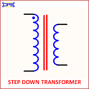
For example, a step -down transformer can convert 230V AC into 12V AC, 9V AC, or 6V AC depending on its design. It is widely used in power supplies, embedded systems, battery chargers, control panels, electronic equipment, and laboratory circuits.
Basic Concept Behind a Step -Down Transformer
A transformer transfers electrical energy from one circuit to another through electromagnetic induction. A step -down transformer contains two electrically isolated windings known as the primary winding and secondary winding.
The primary winding is connected to the higher AC input voltage, while the secondary winding provides the reduced AC output voltage.
In a step- down transformer:
Number of primary turns > Number of secondary turns
Therefore, the secondary voltage is lower than the primary voltage.
How Voltage Reduction Takes Place
When alternating voltage is applied to the primary winding, alternating current produces a changing magnetic flux in the transformer core.
This magnetic flux links with the secondary winding and induces an AC voltage. Since the secondary winding contains fewer turns than the primary winding, the induced secondary voltage is lower.
The voltage relationship can be expressed as:
Vp / Vs = Np / Ns
Where:
- Vp = Primary voltage
- Vs = Secondary voltage
- Np = Number of primary turns
- Ns = Number of secondary turns
For example, a transformer designed for 230V AC input and 12V AC output significantly reduces the mains voltage before it is rectified and regulated for an electronic circuit.
Inside the Transformer
A typical step -down transformer consists of several important parts.
Primary Winding
The primary winding receives the high-voltage AC input supply.
Secondary Winding
The secondary winding provides the required lower AC output voltage.
Magnetic Core
The core provides a low-reluctance path for magnetic flux between the windings. Laminated cores are commonly used to reduce eddy-current losses.
Insulation
Insulating materials electrically separate the windings and help provide safe operation.
Transformer Frame
The outer structure supports and protects the windings and core.
Input-to-Output Conversion Example
Consider a transformer with:
Input: 230V AC
Output: 12V AC
When 230V AC is connected to the primary side, electromagnetic induction produces approximately 12V AC across the secondary winding according to the transformer’s turns ratio.
The 12V AC can then be connected to a bridge rectifier, filter capacitor, and voltage regulator to obtain a suitable DC voltage for electronic circuits.
Role in a DC Power Supply
A step- down transformer is frequently used as the first stage of a traditional linear DC power supply.
The power conversion sequence is:
230V AC → Step Down Transformer → Low-Voltage AC → Rectifier → Filter → Voltage Regulator → DC Output
For example:
230V AC → 12V AC → Rectification → Filtering → 5V DC
The resulting 5V DC can be used to power microcontrollers, sensors, LCD modules, and other low-voltage electronics.
Important Electrical Parameters
| Parameter | Typical Specification |
|---|---|
| Input Voltage | 230V AC |
| Output Voltage | 6V / 9V / 12V / 24V AC |
| Frequency | 50/60 Hz |
| Transformer Type | Step Down |
| Windings | Primary and Secondary |
| Core | Laminated Magnetic Core |
| Output | Low-Voltage AC |
| Isolation | Primary-to-Secondary Isolation |
The exact ratings depend on the transformer model and intended application.
Common Step Down Transformer Ratings
Step -down transformers are manufactured in different voltage and current ratings.
Common examples include:
- 230V to 6V
- 230V to 9V
- 230V to 12V
- 230V to 15V
- 230V to 18V
- 230V to 24V
- 230V to 12-0-12V
The required transformer should be selected according to the voltage, current, power, and isolation requirements of the circuit.
Why Step- Down Transformers Are Useful
A properly selected transformer provides several benefits:
- Reduces high AC voltage to a usable level
- Provides electrical isolation in isolated transformer designs
- Simple and reliable operation
- Suitable for many power-supply circuits
- Available in different voltage and current ratings
- Requires no complex control circuitry
- Useful for embedded and electronic projects
Where Step Down Transformers Are Used
Step down transformers are found in numerous electrical and electronic systems, including:
- DC power supplies
- Battery chargers
- Embedded system development boards
- Industrial control circuits
- Doorbell circuits
- Audio equipment
- Laboratory power supplies
- Automation projects
- Control panels
- Low-voltage lighting systems
- Electronic testing equipment
- Educational electronics projects
Importance in Embedded Electronics
Many embedded systems operate at low DC voltages such as 3.3V, 5V, or 12V, while the available mains supply may be 230V AC.
In transformer-based power supplies, the step -down transformer reduces the mains voltage to a safer, lower AC level. The voltage is then rectified, filtered, and regulated before being supplied to the embedded circuit.
This makes the transformer an important part of many traditional microcontroller, sensor, relay, and communication-based projects.
Transformer Losses and Efficiency
A practical transformer cannot transfer all input power to the secondary side without losses. Some energy is lost due to:
- Copper losses in the windings
- Eddy-current losses
- Hysteresis losses
- Leakage magnetic flux
Proper core materials, winding design, and insulation help improve transformer efficiency and reliability.
Selecting a Suitable Transformer
Before choosing a step -down transformer, consider:
- Required primary voltage
- Required secondary voltage
- Output current requirement
- VA or power rating
- Operating frequency
- Isolation requirements
- Physical dimensions
- Mounting method
- Expected load conditions
Selecting the correct rating prevents excessive heating and helps ensure reliable circuit operation.
Safety Considerations
The primary side of a mains step- down transformer can carry dangerous line voltage. Proper insulation, fusing, enclosures, grounding where applicable, and safe clearances should be used.
Students and beginners should avoid working directly with exposed mains wiring without qualified supervision.
Step Up and Step Down Transformer Comparison
| Step Down Transformer | Step Up Transformer |
|---|---|
| Decreases voltage | Increases voltage |
| Secondary has fewer turns | Secondary has more turns |
| Primary voltage is higher | Secondary voltage is higher |
| Common in low-voltage power supplies | Common in voltage-boosting applications |
Final Overview
A step -down transformer is an essential electrical component for converting high AC voltage into a lower AC voltage through electromagnetic induction. Its simple construction, electrical isolation capability, reliability, and availability in various ratings make it useful in power supplies, embedded electronics, automation systems, chargers, and industrial control applications.
Understanding the operation of a step -down transformer also provides a strong foundation for learning about power supplies, rectifiers, voltage regulators, electromagnetic induction, and electrical power conversion.