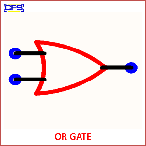
An OR Gate is a fundamental digital logic gate that outputs a logical HIGH (1) if at least one of its inputs is HIGH (1). It performs the logical OR operation and is commonly used in digital electronics to implement decision-making processes.

Key Features of an OR Gate
- Boolean Expression:
- The output (YYY) is expressed as: Y=A+BY = A + BY=A+B where AAA and BBB are the inputs, and the +++ symbol represents the logical OR operation.
- Truth Table:
| Input A | Input B | Output Y (A+BA + BA+B) |
|---|---|---|
| 0 | 0 | 0 |
| 0 | 1 | 1 |
| 1 | 0 | 1 |
| 1 | 1 | 1 |
- Symbol:
- The OR gate is symbolized as a curved input shape converging to a point at the output.
Applications of OR Gate
- Decision-Making Circuits:
- Used in circuits where an action is triggered if one or more conditions are met.
- Control Systems:
- Activates systems when any of several inputs are active.
- Data Transmission:
- Ensures data is passed if one or more signals are present.
- Alarms and Indicators:
- Common in alarm systems where any sensor being triggered activates the alert.
Advantages:
- Simple design and operation.
- Useful in basic and complex logic designs.
Disadvantages:
- Limited to specific operations; other logic gates may be required for complex functionality.
In summary, an OR Gate is a critical building block in digital electronics that outputs a HIGH (1) signal when at least one of its inputs is HIGH, facilitating simple and intuitive decision-making in logic circuits.
