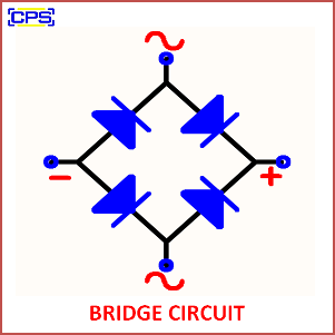
A bridge circuit is an electrical circuit designed to measure an unknown component’s value (such as resistance, capacitance, or inductance) or to perform signal processing tasks. It consists of two voltage dividers connected in parallel, forming a “bridge” structure.

Key Features of a Bridge Circuit:
- Structure:
- Typically consists of four circuit elements (e.g., resistors, capacitors, or inductors) arranged in a quadrilateral.
- A source voltage is applied across two opposite points (input terminals), and the output is measured across the other two points (output terminals).
- Balance Condition:
- The bridge is said to be “balanced” when the voltage difference across the output terminals is zero.
- The balance condition is used to derive the value of an unknown component.
- Types of Bridge Circuits:
- Wheatstone Bridge: Used to measure unknown resistance.
- Maxwell Bridge: Used for measuring inductance.
- Schering Bridge: Used for measuring capacitance.
- AC Bridge Circuits: Used for impedance measurement.
Applications:
- Precision measurement of electrical components.
- Sensor signal conditioning (e.g., strain gauges, temperature sensors).
- Fault detection in electrical circuits.
- Calibration and testing of electronic components.
Bridge circuits are widely used in both DC and AC applications, offering high accuracy and sensitivity in measurements and signal processing tasks.
